하드웨어
모터의 종류와 원리 2 - BLDC모터 - 이론
BLDC 모터는 브러시 대신 ESC로 극성을 전환하는 직류 모터다.
권민재
BLDC 모터란
기존 DC 모터에서는 극전환을 위해 기구적인 트릭(브러시, 정류자)을 사용했었다면,
BLDC 모터는 해당 구조에서 기구적인 요소를 없애고 ESC(Electronic Speed Controller)를 사용하여 극성전환의 기능을 하도록 만든 모터입니다.
BLDC 모터의 종류
BLDC 모터 내에서도 회전부의 위치에 따라 크게 두가지로 분류됩니다.
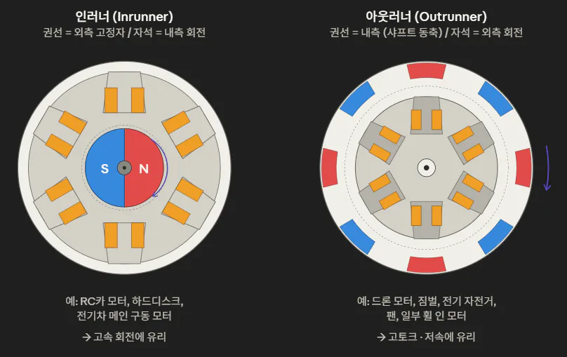
BLDC 모터의 구조
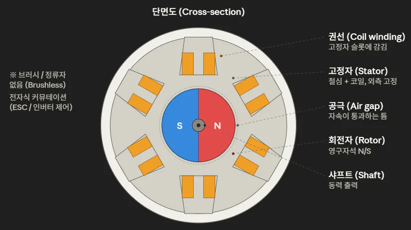
예시중 하나인 인러너 구조로 설명하겠습니다.
BLDC 모터는 크게 세 부분으로 구성됩니다.
회전자(Rotor)
모터의 고정된 부분으로 코일이 감겨있고, 해당부분에 ESC를 통해 전류를 공급받아 자기장을 발생 시킵니다.고정자(Stator)
모터에서 움직이는 부분으로, 영구자석이 위치해있고 코일의 자기장에 영향을 받아 회전합니다.홀센서(Hall Sensor)
기존DC모터는 기구적인 방식으로 알아서 극성이 바뀌었지만,
BLDC 모터에서는 현재 모터가 어느위치에 위치해있는지를 확인하기 위해 홀센서가 사용됩니다.
BLDC 모터의 동작원리

BLDC 모터의 동작원리는 본질적으로 로렌츠 힘(F = IL × B)에 기반하며,
고정자 권선에 흐르는 전류와 회전자 영구자석이 형성하는 자속과 상호작용하여 토크를 발생시킵니다.
코일이 기계적으로 고정되어 있으므로, BIL, 로렌츠 힘의 반작용이 회전자에 작용해 회전 운동으로 나타납니다.
3상 권선(U, V, W)은 전기각 120° 간격으로 배치되며, 각 상에 흐르는 전류는 회전자 위치 θ_e에 따라 정의되는 시퀀스로 전환됩니다.
이상적인 BLDC(사다리꼴 역기전력)의 경우 6-step (120° conduction) 정류가 사용되며, 한 전기 주기당 6개의 스위칭 상태로 회전자기장을 합성합니다.
Step | U | V | W |
|---|---|---|---|
1 | + | - | 0 |
2 | + | 0 | - |
3 | 0 | + | - |
4 | - | + | 0 |
5 | - | 0 | + |
6 | 0 | - | + |
회전자 위치는 홀 센서 3개로 60° 분해능을 얻거나, 센서리스 방식에서는 비통전상의 역기전력 영교차점(zero-crossing)으로 추정합니다.
발생 토크는
정현파 역기전력을 갖는 PMSM의 경우에는 Clarke–Park 변환을 통해 d-q 회전 좌표계로 옮겨,
표면부착형(SPM)에서는
매입형(IPM)에서는 reluctance torque 항을 활용한 MTPA(Maximum Torque per Ampere) 제어가 적용됩니다.
제어 측면에서 BLDC는 일반적으로 6-step 구형파 제어(저비용·간단)가, PMSM은 FOC(Field-Oriented Control) 또는 DTC(Direct Torque Control)가 표준입니다.
다만 산업계에서 "BLDC"와 "PMSM"의 경계는 모호하며, 동일 하드웨어에 어떤 제어 방식을 적용하느냐에 따라 분류가 달라지기도 합니다.
BLDC 모터의 장단점
장점
긴 수명과 유지보수 비용이 낮다.
효율이 높다. (85~95%)
스파크와 전자기 노이즈가 거의 없다.
정밀한 위치제어가 가능하다.(ESC)
크기에 비해 작고 가볍다.
단점
초기비용이 높다.
ESC가 반드시 필요하다.
배선이 3가닥(3상)으로 DC 모터(2가닥) 대비 많다.
제어알고리즘이 복잡하다.
저속에서 전류제어가 불안정해 떨림 이슈가 있다.
BLDC 모터의 특징 및 사용처
구분 | 인러너 (Inrunner) | 아웃러너 (Outrunner) |
|---|---|---|
권선 위치 | 바깥쪽 | 안쪽 |
회전하는 부분 | 안쪽 | 바깥쪽 |
특징 | 고RPM, 저관성 | 저RPM, 고토크 |
사용처 | 전기차 구동, RC카, HDD | 드론, 짐벌, 전기자전거 |
Types and Principles of Motors - BLDC Motors
A BLDC motor is a DC motor that uses an ESC to reverse polarity instead of brushes.
What is a BLDC Motor?
While conventional DC motors used mechanical components (such as brushes and commutators) to switch polarity, a
BLDC motor eliminates these mechanical elements and instead uses an ESC (Electronic Speed Controller) to perform the function of polarity switching.
Types of BLDC Motors
BLDC motors are broadly classified into two types based on the location of the rotating part.
Structure of a BLDC Motor
I will explain using the inrunner structure as an example. A
BLDC motor consists of three main parts.
Rotor: The
stationary part of the motor, wound with coils, which receives current from the ESC to generate a magnetic field.Stator: The stationary
part of the motor, where permanent magnets are located; it rotates in response to the magnetic field generated by the coils.Hall Sensor: While conventional
DC motors relied on mechanical means to automatically switch polarity,
BLDC motors use Hall sensors to determine the motor’s current position.
Operating Principle of a BLDC Motor
The operating principle of a BLDC motor is fundamentally based on the Lorentz force (F = IL × B). It generates torque through the interaction between
the current flowing through the stator windings and the magnetic flux created by the permanent magnets in the rotor. Since
the coils are mechanically fixed, the reaction force of the Lorentz force acts on the rotor, resulting in rotational motion.
The three-phase windings (U, V, W) are arranged at 120° electrical angles, and the current flowing through each phase is switched according to a sequence defined by the rotor position θ_e.
For an ideal BLDC (trapezoidal back-EMF), 6-step (120° conduction) commutation is used, synthesizing the rotor magnetic field into six switching states per electrical cycle.
Step | U | V | W |
|---|---|---|---|
1 | + | - | 0 |
2 | + | 0 | - |
3 | 0 | + | - |
4 | - | + | 0 |
5 | - | 0 | + |
6 | 0 | - | + |
The rotor position is determined using three Hall sensors to achieve 60° resolution, or, in sensorless systems, by estimating the zero-crossing of the back-EMF during the non-conducting phase.
The generated
with sinusoidal back-EMF, the system is transformed into the d-q rotating coordinate system via the Clarke–Park transformation to obtain a
(SPM) configurations
, MTPA (Maximum Torque per Ampere) control utilizing the reluctance torque term is applied.
In terms of control, 6-step square-wave control (low-cost and simple) is generally standard for BLDC motors, while FOC (Field-Oriented Control) or DTC (Direct Torque Control) is standard for PMSM motors.
However, the distinction between "BLDC" and "PMSM" is ambiguous in the industry, and the classification may vary depending on which control method is applied to the same hardware.
Advantages and Disadvantages of BLDC Motors
Advantages
Long service life and low maintenance costs.
High efficiency (85–95%).
Virtually no sparking or electromagnetic noise.
Precise position control is possible (ESC).
Compact and lightweight for its size.
Disadvantages
High initial cost.
An ESC is required.
It has three wires (three-phase), which is more than a DC motor (two wires).
The control algorithm is complex.
Current control is unstable at low speeds, causing vibration issues.
Features and Applications of BLDC Motors
Classification | Inrunner | Outrunner |
|---|---|---|
Winding Position | Outside | Inside |
Rotating part | Inner | Outer |
Features | High RPM, low inertia | Low RPM, high torque |
Applications | Electric vehicle drive, RC cars, HDDs | Drones, gimbals, electric bicycles |