하드웨어
기어의 종류 2 - 교차축 기어
교차축 기어, 직선·스파이럴·제롤 베벨기어의 모든 것
권민재
교차축에 해당하는 기어들에 대해 알아보겠습니다.
분류 | 기어종류 |
|---|---|
교차축 | 직선 베벨기어, 스파이럴 베벨기어, 제로올 기어, 마이터기어 |
직선 베벨기어
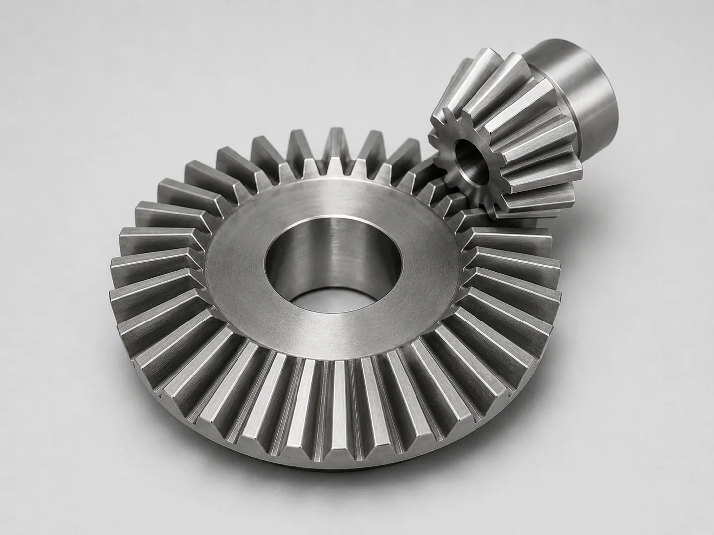
직선 베벨기어는 교차하는 두 축 사이에서 동력을 전달하며, 힘의 방향을 바꾸도록 설계된 기어입니다.
두 축의 교차각은 일반적으로 90°이지만 60°·120° 등으로 조절할 수 있고, 잇수 비율에 따라 감속·방향전환을 함께 구현할 수 있습니다.
그중 두 기어의 잇수가 동일하고 축각이 90°로 고정된 형태를 마이터 기어(Miter Gear) 라고 하며, 1:1 비율로 방향만 전환하는 용도로 사용됩니다.
잇줄(치선)이 원뿔의 꼭짓점 방향으로 곧게 뻗어 있는 것이 구조적 특징입니다.
이 때문에 맞물림이 한 번에 시작되어 한 번에 끝나므로, 구조가 단순하고 가공이 용이한 반면 고속 회전 시 충격성 접촉으로 소음과 진동이 발생합니다.
따라서 주로 저속~중속 영역에서 사용되며, 이러한 한계를 보완하기 위해 등장한 것이 다음에 소개할 스파이럴 베벨기어입니다.
스파이럴 베벨기어
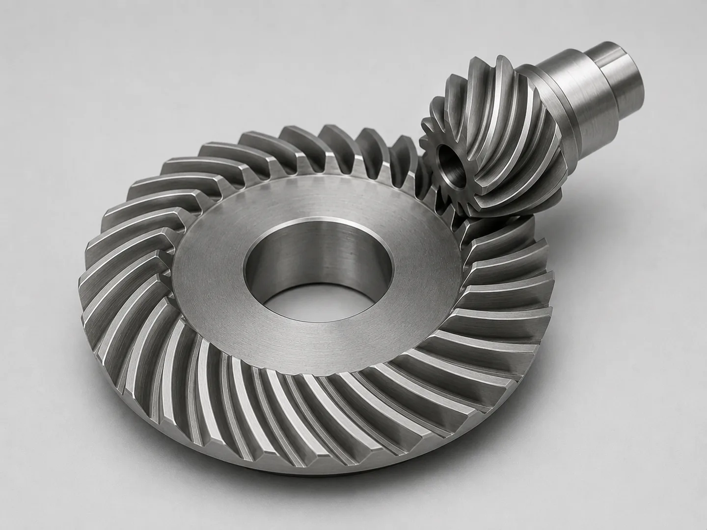
스파이럴 베벨기어는 평행축 기어 파트에서 다룬 헬리컬 기어와 같은 원리로, 잇줄에 나선각(spiral angle)을 부여하여 만든 기어입니다.
이를 통해 기존 직선형에 비해 맞물림이 단계적으로 이루어져 진동·소음이 크게 개선되며, 동시에 두 개 이상의 이가 항상 접촉 상태를 유지하게 되어
동일 크기에서 더 큰 토크를 전달할 수 있습니다. 이러한 특성 덕분에 고속·고하중 영역에서 주로 사용되며, 대표적인 적용 예가 자동차 디퍼렌셜 기어입니다.
단점 또한 헬리컬 기어와 동일하게 나타납니다.
나선각으로 인해 축방향 추력(thrust) 이 발생하므로, 이를 지지하기 위한 스러스트 베어링이 필수적이며, 기어 가공 또한 직선 베벨보다 복잡하고 비용이 높습니다.
제롤 베빌기어
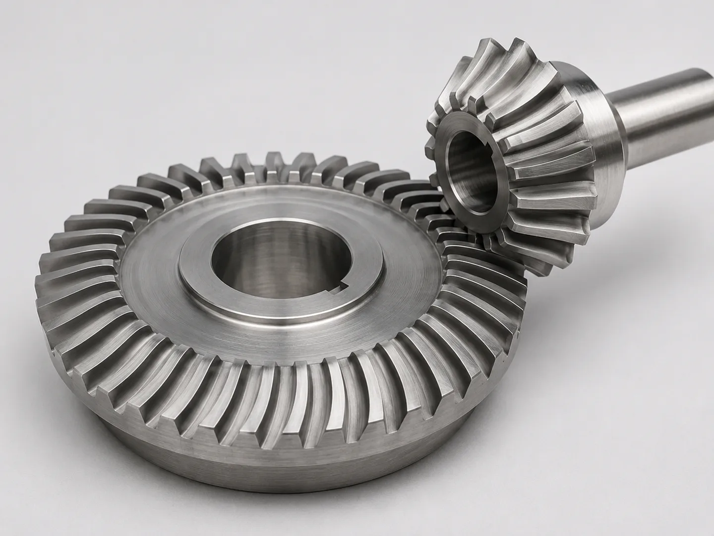
제롤 베벨기어는 잇을 곡선(원호) 형태로 가공하되 나선각은 0°로 유지한 베벨기어입니다.
직선 베벨과 스파이럴 베벨의 중간 단계에 위치하고 있습니다.
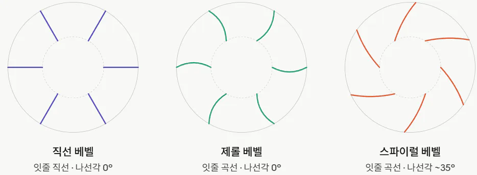
잇줄이 곡선이라는 점에서 직선 베벨보다 맞물림이 단계적으로 이루어져 진동·소음이 개선되지만, 나선각이 0°이므로 축방향 추력이 거의 발생하지 않아
스파이럴 베벨과 달리 별도의 스러스트 베어링이 필요하지 않습니다. 항공기 보조 구동계나 정밀 감속기처럼 고정밀·고경도가 요구되는 용도에 주로 사용됩니다.
별도로 자동차 차동기어에 사용되는 구조이기에 영상참고하시면 좋을 것 같습니다.
Types of Gears 2 - Cross-Shaft Gears
Explore cross-shaft gears: straight, spiral, and Gerol bevel gears.
Let's take a look at the gears on the cross shaft.
Classification | Types of Gears |
|---|---|
Crossed Axes | Straight bevel gears, spiral bevel gears, zero-lead gears, miter gears |
Straight Bevel Gears
Straight bevel gears transmit power between two intersecting shafts and are designed to change the direction of force. The angle between
the two axes is typically 90°, but it can be adjusted to 60°, 120°, etc., and depending on the gear ratio, both speed reduction and direction reversal can be achieved simultaneously.
Among these, the type where both gears have the same number of teeth and the axis angle is fixed at 90° is called a miter gear, which is used solely for direction reversal at a 1:1 ratio.
A structural characteristic of this gear is that the tooth line extends straight toward the apex of the cone.
Because meshing begins and ends simultaneously, the structure is simple and easy to manufacture; however, high-speed rotation results in impact contact, causing noise and vibration.
Therefore, they are primarily used in the low- to medium-speed range. To compensate for these limitations, the spiral bevel gear—which will be introduced next—was developed.
Spiral Bevel Gear
Spiral bevel gears operate on the same principle as helical gears, which were covered in the section on parallel-axis gears; they are gears created by applying a spiral angle to the tooth profile.
This allows meshing to occur in stages compared to conventional straight-tooth gears, significantly reducing vibration and noise. At the same time, two or more teeth remain in constant contact, enabling the transmission of greater torque for the same size. Thanks to these characteristics, they are primarily used in high-speed and high-load applications, with a typical example being automotive differential gears.
However, they share the same disadvantages as helical gears.
Because the spiral angle generates axial thrust, thrust bearings are essential to support it, and gear machining is more complex and costly than that of straight bevel gears.
Geroll Bevel Gear
A Gerol bevel gear is a bevel gear machined with a curved (arc-shaped) tooth profile while maintaining a helix angle of 0°. It occupies an intermediate position between straight bevel gears and spiral bevel gears.
Because the tooth profile is curved, meshing occurs in stages, which improves vibration and noise compared to straight bevel gears; however, since the helix angle is 0°, almost no axial thrust is generated, so unlike spiral bevel gears, a separate thrust bearing is not required. They are primarily used in applications requiring high precision and high hardness, such as aircraft auxiliary drive systems or precision reducers.