하드웨어
기어의 종류 4 - 특수기어
특수 기어의 세계: 유성, 하모닉, 사이클로이드 기어 파헤치기
권민재
기어의 종류 중 마지막인 특수 기어에 대해서 알아보겠습니다.
분류 | 기어종류 |
|---|---|
특수기어 | 유성기어, 하모닉드라이브, 사이클로이드기어 |
유성기어
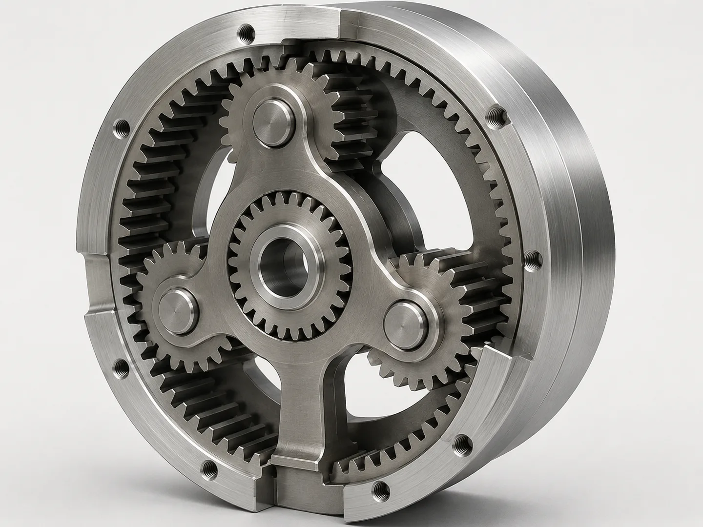
유성기어는 중심에 있는 선기어와 바깥쪽 링기어 사이에 여러 개의 유성기어가 배치되고, 이 유성기어들이 캐리어에 의해 연결된 구조의 기어 시스템입니다.
태양 주위를 행성이 도는 모습과 닮아 "유성(planet)" 이라는 이름이 붙었습니다.
세 요소(선기어, 캐리어, 링기어) 중 어느 하나를 고정하고 어느 하나를 입력으로 두느냐에 따라 감속비와 회전 방향이 달라지는 것이 가장 큰 특징입니다.
동일한 구조로 감속·증속·역전이 모두 구현 가능하며, 자동변속기로 사용되기도 합니다.
장점은 하중이 여러 개의 유성기어로 분산되어 같은 크기에서 일반 평기어 대비 훨씬 큰 토크를 전달할 수 있습니다.
입력축과 출력축이 동심으로 배치되어 축 정렬이 단순하고 공간 효율이 높으며, 단을 직렬로 연결해 고감속비(1:1000 이상)도 작게 구현할 수 있습니다.
단점은 구조가 복잡해 부품 수가 많고 제작·조립 난이도가 높습니다.
각 유성기어 간 하중 균등 분배가 제대로 이루어지지 않으면 일부 기어에 응력이 집중되어 수명이 짧아질 수 있습니다.
로봇 관절 감속기 고하중·고감속·동축 입출력이 필요한 거의 모든 분야에서 사용되는 가장 보편적인 고성능 기어 시스템입니다.
하모닉드라이브
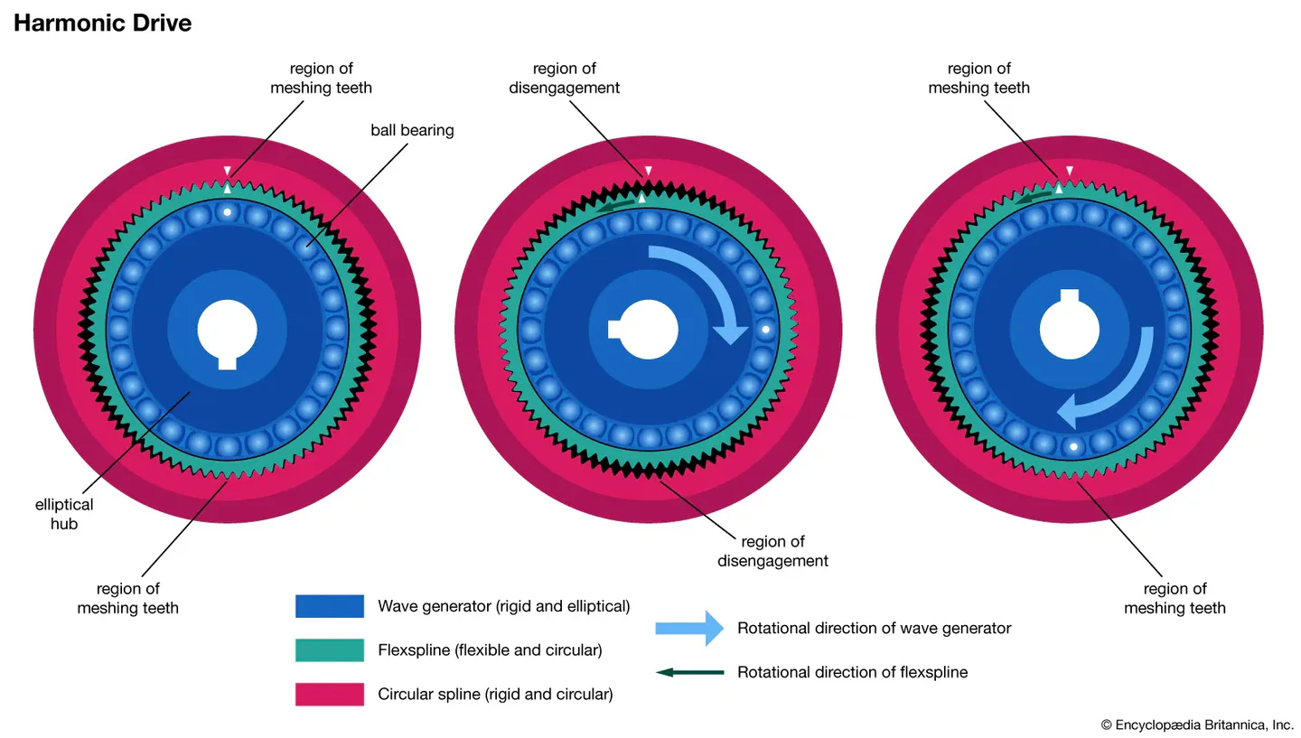
하모닉 드라이브는 금속의 탄성 변형을 이용해 동력을 전달하는 특수한 감속기입니다.
일반적인 기어가 단단한 부품 간의 맞물림으로 동작하는 것과 달리, 하모닉 드라이브는 탄성 부품을 변형시켜 맞물림을 만든다는 점이 다릅니다.
부품 | 역할 |
|---|---|
웨이브 제너레이터 | 타원형 캠 + 베어링. 회전하면서 플렉스 스플라인을 타원으로 변형시킴 |
플렉스 스플라인 | 얇은 링 모양의 탄성 외치 부품. 타원으로 변형되며 회전 |
서큘러 스플라인 | 강체 링 모양의 내치부품. 일반적으로 고정되어져 있음 |
작동 원리
플렉스 스플라인의 잇수는 서큘러 스플라인보다 2개 적게 설계됩니다.
웨이브 제너레이터가 플렉스 스플라인을 타원으로 변형시키면, 타원의 장축 양 끝에서만 두 스플라인의 이가 맞물리고, 단축 부근에서는 이가 떨어집니다.
웨이브 제너레이터가 한 바퀴 돌면 맞물림 지점이 한 바퀴 이동하고, 그 결과 플렉스 스플라인은 잇수 차이(2개)만큼만 반대 방향으로 회전합니다.
즉 입력이 한 바퀴 도는 동안 출력은 2/202 -> 1% 만 회전 — 단일 단으로 1:50 ~ 1:320의 높은 감속비가 구현됩니다.
장점
제로 백래시(zero backlash) — 타원 변형으로 항상 다수의 잇이 접촉 상태이고, 탄성 예압이 백래시를 흡수함. 정밀 위치 제어가 필수인 로봇 관절에서 결정적 장점.
고감속비 + 컴팩트 — 단일 단으로 1:100 수준을 얇은 디스크 형태로 구현. 동일 감속비의 유성기어 다단 구조보다 훨씬 가볍고 얇음.
동축 입출력 — 입출력이 같은 축 위에 있어 로봇 관절 구조에 그대로 들어감.
높은 토크 밀도 — 다수의 잇이 동시 접촉 상태이므로 단위 부피당 토크가 매우 큼.
단점
탄성 변형 의존 → 비틀림 강성(torsional stiffness)이 낮음 — 고하중에서 미세한 위치 오차(windup)가 발생. 정밀 제어 시 토크-각도 보상이 필요.
플렉스 스플라인의 피로 한계 — 매 회전마다 탄성 변형이 반복되므로 수명이 사이클 수에 의해 제한됨.
고가 — 정밀 가공이 필수이고 시장이 사실상 독점 구조(일본 Harmonic Drive Systems Inc.)라 가격이 매우 높음.
주 사용처
산업용·협동로봇의 관절 감속기로 사실상 표준입니다. Universal Robots, KUKA iiwa, 두산 로보틱스 등 대부분의 협동로봇이 관절마다 하모닉 드라이브를 사용합니다.
그 외에도 고정밀·저백래시가 요구되는 분야에 폭넓게 사용됩니다.
협동로봇 관절을 분해하면 약 80-90%가 하모닉 드라이브를 쓰고 있을 정도로 로봇공학의 표준 부품입니다.
이 부품의 특성(저강성·고감속·제로백래시)은 모델링 단계에서 반드시 고려해야 하는 트레이드오프라 알고 있으면 좋을 것 같습니다.
특히 flexible joint model이 하모닉 드라이브로 인해 생긴 솔루션인데, 짧게 설명하자면
사이클로이드기어

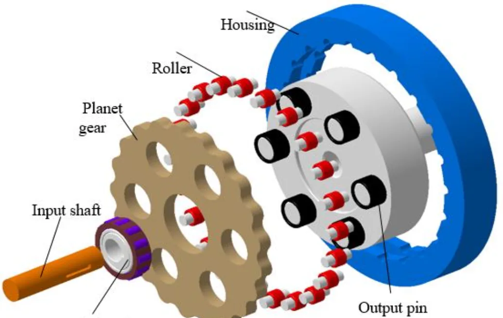
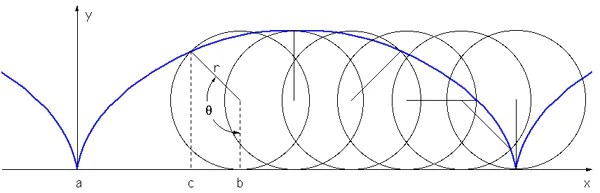
사이클로이드 감속기는 잇면 형상이 사이클로이드 곡선으로 가공된 디스크가 편심 회전하면서 동력을 전달하는 감속기입니다.
에피사이클로이드(epicycloid) 또는 하이포사이클로이드(hypocycloid) 형상을 활용하며, 산업용 로봇과 정밀 감속기의 핵심 부품으로 사용됩니다.
부품 | 역할 |
|---|---|
입력축 (편심캠) | 모터에 연결, 편심 회전을 만듦 (입력) |
사이클로이드 디스크 | 사이클로이드 잇면을 가진 디스크. 편심캠 위에서 흔들리듯 회전 |
고리핀 (Ring Pin) | 하우징 안쪽에 배치된 핀들. 디스크 외주와 맞물려 회전을 구속 |
출력 핀/롤러 | 디스크의 회전을 출력축으로 전달 (출력) |
입력축의 편심캠이 회전하면 사이클로이드 디스크가 편심 운동을 하면서 고리핀과 맞물립니다.
디스크의 잇수는 고리핀 개수보다 정확히 1개 적게 설계되며, 편심캠이 한 바퀴 도는 동안 디스크는 반대 방향으로 1개 잇만큼만 회전합니다.
일반적으로 단일 단에서 1:10 ~ 1:200 수준의 감속비가 구현됩니다.
장점
다수의 이가 동시 접촉 (60~70%) — 사이클로이드 디스크는 어느 순간에도 전체 고리핀의 절반 이상과 동시에 접촉합니다.
일반 평기어가 한두 개의 이로 하중을 받는 것과 대비되며, 이로 인해 토크 밀도가 매우 높고 충격 하중에 강함.백래시가 거의 없음 — 다수 잇 동시 접촉 + 정밀 가공으로 백래시가 1 arcmin 이하 수준까지 가능.
높은 비틀림 강성 — 하모닉 드라이브와 달리 탄성 변형 요소가 없어 강체에 가까운 거동. 급가속 시에도 진동이 적고 위상 지연이 작음.
높은 효율 (~95%) — 잇면 접촉이 주로 구름 접촉(rolling contact) 이라 미끄럼 손실이 적음.
충격에 강함 — 다수 잇이 하중을 분담하므로 순간적인 과부하에도 잇이 부러지지 않고 견딤. 산업 환경에서 중요한 특성.
단점
편심 회전으로 인한 진동 발생 — 입력축이 편심 회전을 만들기 때문에 불균형 관성력(unbalance) 이 생김.
이를 줄이기 위해 보통 두 개의 사이클로이드 디스크를 180° 위상차로 배치하지만, 완전히 제거되지는 않음.구조가 복잡하고 부품 수가 많음 — 정밀 가공이 필요한 부품(편심캠, 디스크, 고리핀, 출력 핀)이 많아 제작 비용이 높음.
무게와 부피 — 하모닉 드라이브에 비해 두껍고 무거움. 휴머노이드처럼 분산 질량이 중요한 응용에는 불리.
고속 회전에 부적합 — 편심 운동의 관성력이 속도 제곱에 비례해 커지므로 고RPM 입력에는 진동·소음이 증가. 보통 입력 3000RPM 이하에서 사용.
가볍고 얇아야 한다 → 하모닉 (협동로봇 관절)
충격을 견디고 강성이 높아야 한다 → 사이클로이드 (산업용 로봇 베이스 관절)
주 사용처
산업용 6축 로봇의 어깨·허리 관절에 사실상 표준입니다. ABB, FANUC, KUKA, 야스카와 등 주요 산업용 로봇 제조사가 큰 관절(J1, J2, J3)에는
사이클로이드 감속기를 사용합니다. 손목 부분(J4, J5, J6)은 무게가 중요해서 하모닉을 쓰기도 합니다. 고하중·고강성·충격 부하가 요구되는 분야에 사용됩니다.
Types of Gears 4 - Special Gears
The World of Specialized Gears: A Deep Dive into Planetary, Harmonic, and Cycloidal Gears
Let’s take a look at special gears, the final type of gear.
Classification | Types of Gears |
|---|---|
Special Gears | Planetary Gears, Harmonic Drives, Cycloidal Gears |
Planetary Gears
A planetary gear system consists of a central sun gear and an outer ring gear, with several planetary gears arranged between them, all connected by a carrier. It is named "planetary" because its structure resembles the movement of planets orbiting the sun.
Its most distinctive feature is that the reduction ratio and direction of rotation vary depending on which of the three elements (sun gear, carrier, and ring gear) is fixed and which serves as the input. With the same structure, reduction, speed increase, and reverse rotation can all be achieved, and it is also used in automatic transmissions.
The advantage is that the load is distributed across multiple planetary gears, allowing it to transmit much greater torque than a standard spur gear of the same size.
Since the input and output shafts are coaxially arranged, shaft alignment is simple and space efficiency is high; furthermore, by connecting stages in series, very high reduction ratios (1:1000 or higher) can be achieved.
The disadvantages include a complex structure with many components, making manufacturing and assembly difficult.
If the load is not evenly distributed among the planetary gears, stress may concentrate on certain gears, potentially shortening their service life.
Robot Joint Reducer This is the most common high-performance gear system used in nearly all fields requiring high load capacity, high reduction ratios, and coaxial input and output.
Harmonic Drive
A harmonic drive is a special type of reducer that transmits power by utilizing the elastic deformation of metal.
Unlike conventional gears, which operate through the meshing of rigid components, a harmonic drive differs in that it creates meshing by deforming an elastic component.
Components | Role |
|---|---|
Wave Generator | Elliptical cam + bearing. Rotates to deform the flex spline into an elliptical shape |
Flex Spline | A thin, ring-shaped elastic outer component. Deforms into an ellipse while rotating |
Circular Spline | Rigid ring-shaped inner component. Typically fixed in place |
Operating Principle
The number of teeth on the flex spline is designed to be two fewer than that of the circular spline. When the wave generator deforms the flex spline into an ellipse, the teeth of the two splines mesh only at both ends of the ellipse’s major axis, while they disengage near the minor axis.
When the wave generator rotates one full revolution, the meshing point moves one full revolution, and as a result, the flex spline rotates in the opposite direction by only the difference in the number of teeth (2).
In other words, while the input rotates one full revolution, the output rotates only 2/202 -> 1% — achieving a high reduction ratio of 1:50 to 1:320 in a single stage.
Advantages
Zero backlash — Due to the elliptical deformation, multiple teeth are always in contact, and elastic preload absorbs any backlash. This is a decisive advantage for robot joints where precise position control is essential.
High reduction ratio + compact — Achieves a reduction ratio of approximately 1:100 in a single stage using a thin disk design. It is significantly lighter and thinner than a multi-stage planetary gear structure with the same reduction ratio.
Coaxial input/output — Since the input and output are on the same axis, it integrates seamlessly into robot joint structures.
High torque density — Since multiple teeth are in simultaneous contact, the torque per unit volume is very high.
Disadvantages
Dependence on elastic deformation → Low torsional stiffness — Fine positional errors (windup) occur under high loads. Torque-angle compensation is required for precise control.
Fatigue limit of flex splines — Since elastic deformation repeats with every rotation, service life is limited by the number of cycles.
High cost — Precision machining is essential, and the market is effectively a monopoly (Japan’s Harmonic Drive Systems Inc.), resulting in very high prices.
Main Applications
They are the de facto standard as joint reducers for industrial and collaborative robots. Most collaborative robots, such as those from Universal Robots, KUKA iiwa, and Doosan Robotics, use harmonic drives in each joint.
They are also widely used in fields requiring high precision and low backlash.
Harmonic drives are such a standard component in robotics that when you disassemble a collaborative robot joint, you’ll find they account for about 80–90% of the parts.
It’s helpful to understand that the characteristics of this component—low stiffness, high reduction ratio, and zero backlash—represent trade-offs that must be considered during the modeling phase.
In particular, the “flexible joint model” is a solution derived from harmonic drives; to explain briefly,
Cycloid gear
A cycloidal reducer is a type of reducer that transmits power through the eccentric rotation of a disk machined with a cycloidal curve.
It utilizes epicycloidal or hypocycloidal shapes and is used as a core component in industrial robots and precision reducers.
Components | Role |
|---|---|
Input Shaft (Eccentric Cam) | Connects to the motor, generates eccentric rotation (input) |
Cycloid disk | A disk with a cycloidal tooth profile. Rotates in a wobbling motion on the eccentric cam |
Ring Pin | Pins located inside the housing. Engages with the outer circumference of the disk to constrain its rotation |
Output pin/roller | Transmits the rotation of the disk to the output shaft (output) |
When the eccentric cam on the input shaft rotates, the cycloid disk performs an eccentric motion and meshes with the ring pins. The number of teeth on the disk is designed to be exactly one less than the number of ring pins; during one revolution of the eccentric cam, the disk rotates in the opposite direction by exactly one tooth.
Generally, a reduction ratio of 1:10 to 1:200 is achieved in a single stage.
Advantages
Multiple teeth in simultaneous contact (60–70%) — The cycloidal disk is in contact with more than half of the total teeth on the gear ring at any given moment. This contrasts with standard spur gears, which bear loads on only one or two teeth, resulting in very high torque density and resistance to shock loads.Virtually no backlash — Thanks to simultaneous contact of multiple teeth and precision machining, backlash can be reduced to less than 1 arcminute.
High torsional stiffness — Unlike harmonic drives, there are no elastic deformation elements, resulting in behavior close to that of a rigid body. Vibration is low and phase lag is minimal even during rapid acceleration.
High efficiency (~95%) — Since tooth contact is primarily rolling contact, there is little sliding loss.
Impact resistance — Since multiple teeth share the load, the teeth do not break even under momentary overloads. This is a critical characteristic in industrial environments.
Disadvantages
Vibration caused by eccentric rotation — Since the input shaft creates eccentric rotation, unbalanced inertial forces (unbalance) occur. To reduce this, two cycloid discs are typically arranged with a 180° phase difference, but it cannot be completely eliminated.Complex structure and numerous components — Manufacturing costs are high due to the large number of parts requiring precision machining (eccentric cam, disks, go-pin, output pin).
Weight and size — Thicker and heavier than harmonic drives. Disadvantageous for applications where distributed mass is critical, such as in humanoids.
Unsuitable for high-speed rotation — Since the inertial force of the eccentric motion increases proportionally to the square of the speed, vibration and noise increase at high RPM inputs. Typically used at input speeds of 3000 RPM or less.
Must be lightweight and thin → Harmonic (collaborative robot joints)
Must withstand shocks and have high rigidity → Cycloidal (base joints for industrial robots)
Main Applications
It is the de facto standard for shoulder and waist joints in industrial 6-axis robots. Major industrial robot manufacturers such as ABB, FANUC, KUKA, and Yaskawa use cycloidal reducers for large joints (J1, J2, J3). For the wrist section (J4, J5, J6), where weight is a critical factor, harmonic drives are sometimes used. They are used in applications requiring high load capacity, high rigidity, and shock resistance.